Hebrews 13:5 (New International Version)
"Keep your lives free from the love of money and be content with what you have, because God has said,
"Never will I leave you;
never will I forsake you."

| Outside plant cable is constructed to withstand immersion in water, will resist exposure to ultraviolet rays, and is protected from rodents and birds. |
Fiber strands are placed in a large (relatively) diameter tube and allowed to "float" with considerable movement. As the fiber cable is pulled into place (in conduit, directly buried, or placed on a pole) the strands are not subjected to the forces of the pulling tension. The strands therefore sustain minimal damage or distortion from stretching.
Fiber cables are (as are all communications cables) manufactured based on their intended use. Each cable will have a standard set of markings indicating its primary use, the name of the manufacturer a National Electrical Code rating and a UL approval code, the number of fibers contained within the cable, the outside diameter of the cable, and the manufacturer's product nomenclature. All of these items should be checked when the cable is delivered to a storage area and then at the job-site before the cable is installed.


Fiber Cable Color Identification Chart
Buffer Tube / Fiber Strand Number Color
1 Blue
2 Orange
3 Green
4 Brown
5 Slate
6 White
7 Red
8 Black
9 Yellow
10 Violet
11 Rose
12 Aqua
13 Blue/Black Tracer
14 Orange/Black Tracer
15 Green/Black Tracer
16 Brown/Black Tracer
17 Slate/Black Tracer
18 White/Black Tracer
19 Red/Black Tracer
20 Black/Yellow Tracer
21 Yellow/Black Tracer
22 Violet/Black Tracer
23 Rose/Black Tracer
24 Aqua/Black Tracer
Prepare to Share
Connect computers to each other or to Internet
To share between computers that are at the same location, connect them to an Ethernet network or an AirPort network. For more information, see technical document 106658: "Creating a Small Ethernet Network"
You may also share over the Internet. A single computer using any kind of modem to connect to the Internet can share files, but the "Connecting between remote networks" section below applies.
Computers need IP addresses
If you can connect to the Internet, then your computer already has an IP address that is valid for your network. But if your computer does not have a valid IP address, which you can check in the Network pane of System Preferences, see technical document 106659: "Mac OS: How to Get an IP Address for Connecting to the Internet"
Connecting to the Internet and a local network (or LAN) at the same time
In most cases, users of institutional networks and home broadband will be advised to have their networks set up in a way that makes this goal effortless. Home users who don't have some type of routing device should see How to Connect to the Internet and Share Files Locally at the Same Time.
File Sharing with other Apple operating systems
This article concentrates only on File Sharing for Mac OS X. When properly set up, various Apple operating systems (such as Mac OS X, Mac OS 9, and AppleShare IP) can connect with each other. Be aware that the sharing service has other names, such as AppleShare and Apple File Protocol (AFP). When you connect to any of them, their behavior is superficially the same. If you use AppleTalk, review the AppleTalk issues section below.
Sharing with non-Apple operating systems
This article describes the most simple form of sharing available to Macintosh users (AppleShare). Other methods are available for communicating with other operating systems. See technical documents:
106660: "Mac OS X: Sharing With Non-Apple Operating Systems"
19652: "Macintosh: Networking With a Windows PC"
Connecting between remote networks
Mac OS X can share over the Internet (TCP/IP), as can Mac OS 9 and AppleShare IP. This allows Macintosh computers in remote locations to share files with any type of Internet connection. For more information, see technical document 106661: "Mac OS: Sharing Between Remote Networks, Sharing Over the Internet"
All Public folders are shared. Only Public folders are shared.
See technical document 106662: "Mac OS X: Only Public Folders Are Shared"
File Sharing is for up to 10 users
Up to 10 users may connect to File Sharing simultaneously. If you need to connect more users at once, you should upgrade to Unlimited-Client version of Mac OS X Server (http://www.apple.com/server/).
II. Start Sharing
1. Place files to share in your Public folder.
2. Choose System Preferences from the Apple menu. See Note 1.
3. Click the Network icon.
4. Choose the port you are going to share on (Built-in Ethernet or AirPort) from the Show pop-up menu. See Note 2.
5. Click the AppleTalk tab.
6. Click the checkbox to select Make AppleTalk Active.
7. Click Apply Now.
8. Click the Show All button in the upper left corner of the window.
9. Click the Sharing icon.
10. In the Computer Name field, type the name you wish to appear on the network for your computer. See Note 3.
11. Click Start in the File Sharing section. For Mac OS X 10.2 and later, select Personal File Sharing.
Repeat this process on any other Mac OS X computer that you wish to receive File Sharing connections.
Notes:
1. Users sharing between remote locations skip steps 3 to 8. Users of dial-up must connect before step 11.
2. Prior to Mac OS X 10.1, the Show menu was named "Configure."
3. If you change your Computer Name in the future, you must stop and restart File Sharing for the name change to take effect.
Managing privileges for shared data
Optionally, you can change the access privileges for items in your Public folder.
To change privileges for your entire Public folder:
1. Select your Public folder in a Finder window.
2. Choose Get Info (or Show Info) from the File menu.
3. Set the Show pop-up menu to Privileges.
4. You may now adjust user access privileges for the folder.
You can use the same steps for items in the Public folder.
III. Connect to a Sharing computer
How you connect to a Mac OS X computer that is sharing depends on two major factors:
The steps you need to follow are found in technical document 107369, "Mac OS: How to Connect to File Sharing or Apple File Services (AFP)".
IV. Troubleshooting
AppleTalk issues
Mac OS 8, Mac OS 9, and Mac OS X 10.1 to 10.3.9 support file sharing (AFP) connections over AppleTalk. However, Mac OS X versions 10.0 to 10.0.4 (more) and 10.4 and later (more) can only connect to AppleShare over TCP/IP.
If you want to connect from versions 10.1 to 10.3.9 to Mac OS 8 sharing (which is AppleTalk only), be sure to enable AppleTalk as described in steps 5 and 6 in Section II, above. Mac OS 9 and Mac OS X can both connect over TCP/IP without AppleTalk, so this step is optional in the absence of Mac OS 8.
Mac OS X 10.4 and later don't support Personal File Sharing (or other AFP) over Appletalk, though by initiating the connection from the opposite direction you could still achieve an IP connection from a Mac OS 8 computer to a sharing Mac OS X computer. The Network preference pane in Mac OS X 10.4 and later still offers the AppleTalk checkbox, but it is for browsing AppleTalk-advertised resources and zones. The subsequent connection must be over TCP/IP.
General troubleshooting steps:
Buy Core Spare Parts
Service Parts Management is the main component of a complete strategic service management process that companies use to ensure that right spare part and resources are at the right place (where the broken part is) at the right time.
Strategic Service Management, SSM, is a new customer commitment-centric business strategy that optimizes a company’s service business processes through a single, integrated view of post-sale service operations, by taking into consideration the planning and forecasting of service parts and resources, and the strategy and management of customer commitments, service partners, and service pricing.
Economic Considerations
Spare parts are sometimes considered uneconomical since:
But without the spare part on hand, a company's customer satisfaction levels could drop if a customer has to wait too long for their item to be fixed. Therefore company's need to plan and align their service parts inventory and workforce resources to achieve optimal customer satisfaction levels with minimal costs.
The user of the mechanical item, which might require the parts, may overlook the economic considerations because:
In many cases, where the mechanical item, is not stationary, a compromise is reached between cost and statistical probability. Some examples:
enterprise to OEMs and their service provider partners
Common hardware upgrades are installing additional memory (RAM), adding larger hard disks, replacing microprocessor cards or graphics cards, and installing new versions of software, although many other upgrades are often possible as well.
Common software upgrades include changing the version of an operating system, office suite, anti-virus program, or various other tools.
Common firmware upgrades include the updating of the iPod control menus, the XBox 360 dashboard, or the non-volatile flash memory that contains the embedded operating system for consumer electronics.
Software and firmware upgrades are often downloaded from the Internet. Often the download is a patch—it does not contain the new version of the software in its entirety, just the changes that need to be made. Software patches usually aim to improve functionality or solve problems with security. Rushed patches have been known to cause more harm then good and are therefore sometimes regarded with skepticism for a short time after release. Patches are generally free.
A software or firmware upgrade can be major or minor and the release version is increased accordingly. A major upgrade will change the version number, whereas the minor will usually follow with a ".01", ".02", ".03", etc. For example, version 10.03 means that that is the third minor upgrade of version 10. The minor upgrades (or updates) are generally free, but the major versions must be purchased. See also: sidegrade.
An "upgrade" is when you replace a product with a newer version of that same product. When you make an upgrade of the same product from one company to the other, you are making a "competitive upgrade".
Project control is that element of a project that keeps it on-track, on-time, and within budget. Project control begins early in the project with planning and ends late in the project with post-implementation review, having a thorough involvement of each step in the process. Each project should be assessed for the appropriate level of control needed: too much control is too time consuming, too little control is too costly. If control is not implemented correctly, the cost to the business should be clarified in terms of errors, fixes, and additional audit fees. The practices of project control are part of the field of cost engineering.
Control systems are needed for cost, risk, quality, communication, time, change, procurement, and human resources. In addition, auditors should consider how important the projects are to the financial statements, how reliant the stakeholders are on controls, and how many controls exist. Auditors should review the development process and procedures for how they are implemented. The process of development and the quality of the final product may also be assessed if needed or requested. A business may want the auditing firm to be involved throughout the process to catch problems earlier on so that they can be fixed more easily. An auditor can serve as a controls consultant as part of the development team or as an independent auditor as part of an audit.
Businesses sometimes use formal systems development processes. These help assure that systems are developed successfully. A formal process is more effective in creating strong controls, and auditors should review this process to confirm that it is well designed and is followed in practice. A good formal systems development plan outlines:
To be able to become a good IT manager, you should have the ability to assess the needs of your company, because it is one of your many responsibilities as an IT manager in a company. Having this ability does not matter on what level you are; you just have to develop this kind of ability that will put you in a good position for more responsibility. A good assessment skill can really help you as an IT manager and your company to save thousands of dollars, because there failure of assessing technology means failure of your work as an IT manager which also means useless expense of the company. You should have a good initiative to meet your target and have a profitable expense for the company. It is also important to know the needs of your company to be able to solve the problems. Assessing technology needs plays a major part in helping your career advance, because with this assessing ability you have the edge with other IT managers who have a weak assessment skill. It is your role is to know the real needs of your company especially in technical field as an IT manager. You can easily estimate the worth of the technology with what the company needs. In addition, with this technology the company might achieve their goal or objective. Before going to make an “IT agenda”, it is better to know first the objective and the tangible issues of the company before planning anything, because if you do not know the real issues you might lead to work on the wrong things. If you know what is the goal of the company you can now make a good IT agenda for the company or plans to make the company successful in their line of business.
Typically, LAN-based IP telephones use external power converters located at or near the desktop. The inline-power patch panel eliminates the need for external power sources; it is a standalone chassis that can be co-located with the Catalyst switch to provide -48 VDC power directly to the telephone through existing Catalyst family 10/100BaseTX switching modules. When used with an uninterruptible power supply (UPS), the inline-power patch panel can provide power to the telephone even in a power failure.
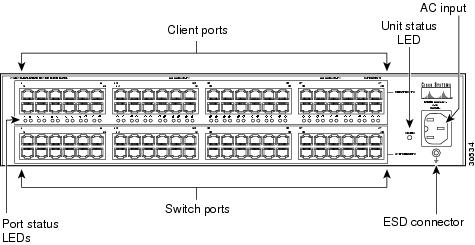
The inline-power patch panel has 48 RJ-45 input ports and 48 RJ-45 output ports (see Figure 1). There are two RJ-45 connectors per port for a total of 48 ports. Each input connector is internally connected to a corresponding output connector (input connector 1 is connected to output connector 1, and so on).
The RJ-45 ports serve as the physical network interfaces to the inline-power patch panel. The lower bank of ports provide 10/100-Mbps connection to the switch through RJ-45 connector pins 1, 2, 3, and 6. The top bank of ports provide -48 VDC power to the IP telephones through RJ-45 connector pins 4, 5, 7, and 8, in addition to transparently passing 10/100 Mbps data traffic on pins 1, 2, 3, and 6.
This section describes the front-panel features of the inline-power patch panel:
•48 RJ-45 client ports for connecting to IP telephones
•48 RJ-45 switch ports for connecting to 10/100BaseTX switch ports
•Unit status LED (see Table 1)
•Port status LED (see Table 2)
•AC-input connector
•ESD receptacle
Figure 1 Inline Power Patch Panel Front Panel
Color | Description |
|---|---|
Green | Power successfully applied to all ports. |
Red | Power problem on one or more ports. |
Off | No AC-input power to inline-power patch panel. |


Typically, LAN-based IP telephones use external power converters located at or near the desktop. The inline-power patch panel eliminates the need for external power sources; it is a standalone chassis that can be co-located with the Catalyst switch to provide -48 VDC power directly to the telephone through existing Catalyst family 10/100BaseTX switching modules. When used with an uninterruptible power supply (UPS), the inline-power patch panel can provide power to the telephone even in a power failure.
The inline-power patch panel has 48 RJ-45 input ports and 48 RJ-45 output ports (see Figure 1). There are two RJ-45 connectors per port for a total of 48 ports. Each input connector is internally connected to a corresponding output connector (input connector 1 is connected to output connector 1, and so on).
The RJ-45 ports serve as the physical network interfaces to the inline-power patch panel. The lower bank of ports provide 10/100-Mbps connection to the switch through RJ-45 connector pins 1, 2, 3, and 6. The top bank of ports provide -48 VDC power to the IP telephones through RJ-45 connector pins 4, 5, 7, and 8, in addition to transparently passing 10/100 Mbps data traffic on pins 1, 2, 3, and 6.
This section describes the front-panel features of the inline-power patch panel:
•![]() 48 RJ-45 client ports for connecting to IP telephones
48 RJ-45 client ports for connecting to IP telephones
•![]() 48 RJ-45 switch ports for connecting to 10/100BaseTX switch ports
48 RJ-45 switch ports for connecting to 10/100BaseTX switch ports
•![]() Unit status LED (see Table 1)
Unit status LED (see Table 1)
•![]() Port status LED (see Table 2)
Port status LED (see Table 2)
•![]() AC-input connector
AC-input connector
•![]() ESD receptacle
ESD receptacle
Figure 1 Inline Power Patch Panel Front Panel
Color | Description |
|---|---|
Green | Power successfully applied to all ports. |
Red | Power problem on one or more ports. |
Off | No AC-input power to inline-power patch panel. |