
Typically, LAN-based IP telephones use external power converters located at or near the desktop. The inline-power patch panel eliminates the need for external power sources; it is a standalone chassis that can be co-located with the Catalyst switch to provide -48 VDC power directly to the telephone through existing Catalyst family 10/100BaseTX switching modules. When used with an uninterruptible power supply (UPS), the inline-power patch panel can provide power to the telephone even in a power failure.
The inline-power patch panel has 48 RJ-45 input ports and 48 RJ-45 output ports (see Figure 1). There are two RJ-45 connectors per port for a total of 48 ports. Each input connector is internally connected to a corresponding output connector (input connector 1 is connected to output connector 1, and so on).
The RJ-45 ports serve as the physical network interfaces to the inline-power patch panel. The lower bank of ports provide 10/100-Mbps connection to the switch through RJ-45 connector pins 1, 2, 3, and 6. The top bank of ports provide -48 VDC power to the IP telephones through RJ-45 connector pins 4, 5, 7, and 8, in addition to transparently passing 10/100 Mbps data traffic on pins 1, 2, 3, and 6.
Front Panel Description
This section describes the front-panel features of the inline-power patch panel:
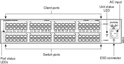
•48 RJ-45 client ports for connecting to IP telephones
•48 RJ-45 switch ports for connecting to 10/100BaseTX switch ports
•Unit status LED (see Table 1)
•Port status LED (see Table 2)
•AC-input connector
•ESD receptacle
Figure 1 Inline Power Patch Panel Front Panel
Color | Description |
|---|---|
Green | Power successfully applied to all ports. |
Red | Power problem on one or more ports. |
Off | No AC-input power to inline-power patch panel. |


PUNCH DOWN TOOL


0 comments:
Post a Comment